
Adafruit HUZZAH32 Feather
| Chip | ESP32-WROOM-32 |
| Dimmers, servos & motors | 16 PWM channels (a motor takes 2) |
| LED strips (WS2812) | up to 8 |
| Battery | built-in LiPo connector and charger; battery level is reported |
| Firmware | esp32-huzzah32, install it from your browser |
Pinout
Section titled “Pinout”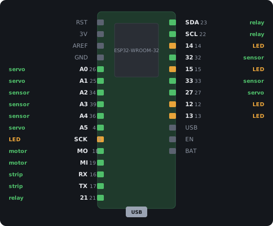
Green pins are good for anything they can do. Amber pins work but have a quirk, so read the note below before putting a relay or motor on one. Red pins are taken by the board itself. Gray pins are power and control (GND, 3V3, EN and so on).
The seller-style pinout with photos: learn.adafruit.com.
Which pin for what
Section titled “Which pin for what”The console marks these with ★ when you assign pins. They are advice. Any pin that can do a job is allowed.
| To connect… | Use | Why |
|---|---|---|
| Servo | A0 A1 A5 27 |
Quiet at power-up, so nothing twitches while the board boots. |
| DC motor (H-bridge IN1/IN2) | MO MI |
A quiet pair side by side for IN1 / IN2 — a motor never lurches at boot. |
| Relay / on-off output | 21 SDA SCL |
Quiet at power-up, so a relay never clicks on during boot. |
| LED strip (WS2812) | RX TX |
Any output can drive a strip. The Feather is 3.3 V with no 5 V pin when on battery — a 5 V strip needs its own supply and a level shifter. |
| LED dimmer (PWM) | SCK 14 15 12 13 |
GPIO 13 is the onboard red LED. The boot-quirk pins (5, 12, 15) suit a light, where a flicker at power-up doesn’t matter. |
| Sensor / button input | A2 A3 A4 32 33 |
A2 / A3 / A4 (GPIO 34 / 39 / 36) are input-only with no pull — fine for PIR and beam sensors. Buttons go on 32 / 33 / 27, which have internal pull-ups. On battery the wake-up sensor goes on one of these. |
Every pin
Section titled “Every pin”| Pin | GPIO | Can be | Note | |
|---|---|---|---|---|
A0 |
26 | ✅ good | input, output, pull-up, pull-down, wakes from sleep | also DAC2 |
A1 |
25 | ✅ good | input, output, pull-up, pull-down, wakes from sleep | also DAC1 |
A2 |
34 | ✅ good | input, analog, wakes from sleep | input only, no internal pull — a button here needs an external resistor |
A3 |
39 | ✅ good | input, analog, wakes from sleep | input only, no internal pull — a button here needs an external resistor |
A4 |
36 | ✅ good | input, analog, wakes from sleep | input only, no internal pull — a button here needs an external resistor |
A5 |
4 | ✅ good | input, output, pull-up, pull-down, analog, wakes from sleep | |
SCK |
5 | ⚠️ caution | output | STRAPPING: pulled high and pulses at power-up — fine for an LED or strip, not for a relay or motor |
MO |
18 | ✅ good | input, output, pull-up, pull-down | |
MI |
19 | ✅ good | input, output, pull-up, pull-down | |
RX |
16 | ✅ good | input, output, pull-up, pull-down | |
TX |
17 | ✅ good | input, output, pull-up, pull-down | |
21 |
21 | ✅ good | input, output, pull-up, pull-down | |
SDA |
23 | ✅ good | input, output, pull-up, pull-down | |
SCL |
22 | ✅ good | input, output, pull-up, pull-down | |
14 |
14 | ⚠️ caution | input, output, pull-up, pull-down, wakes from sleep | pulses briefly at power-up — a relay or motor here may twitch on boot |
32 |
32 | ✅ good | input, output, pull-up, pull-down, analog, wakes from sleep | |
15 |
15 | ⚠️ caution | output | STRAPPING: pulled high and pulses at power-up — fine for an LED or strip, not for a relay or motor |
33 |
33 | ✅ good | input, output, pull-up, pull-down, analog, wakes from sleep | |
27 |
27 | ✅ good | input, output, pull-up, pull-down, wakes from sleep | |
12 |
12 | ⚠️ caution | output | STRAPPING: must be LOW at power-up or the board will not boot. Outputs only, and nothing that pulls it high (many relay modules do) |
13 |
13 | ⚠️ caution | input, output, pull-up, pull-down, wakes from sleep | the onboard red LED shares this pin, and it pulses at power-up — a light, not a relay or motor |
A13 |
35 | ⛔ reserved | battery voltage (VBAT/2) — read by the firmware for the battery gauge | |
TX0 |
1 | ⛔ reserved | USB serial — the console and the flasher live here | |
RX0 |
3 | ⛔ reserved | USB serial — the console and the flasher live here |